GLA-1000B Modification For 10 Meters
After completely removing ALL power from the GLA-1000B, wait 30 minutes for the electronics to discharge thru the bleeder resistors.
*****************
Using the allen wrench supplied with the amplifier, remove the screw on the top of the cabinet near the rear. Also remove all six screws on each side of the unit and remove the top and bottom covers.
*****************
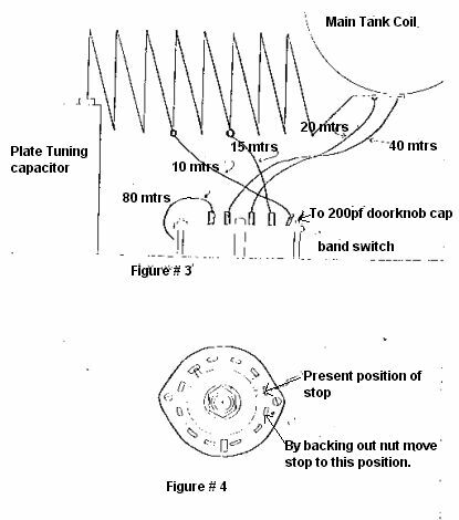
1. Carefully unsolder and remove the 10M and 15M taps from the BAND SWITCH ONLY as shown in figure 3. These are #8 gauge buss wire and should be carefully bent upwards at approximately 45 degrees.
2. Remove the knob on the band selector switch with the allen wrench used for removal of the cabinet screws. Be very careful so as not to scratch the front panel.
3. Remove the nut holding the band switch to the front panel.
4. Carefully push the band switch towards the read of the GLA-1000B while SLIGHTLY bending the remaining wires on the band switch. Push the swithc band only far enough to obtain access to the back of the PC board with a soldering iron.
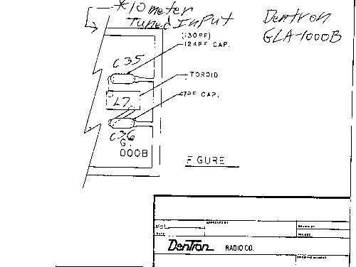
5. Install the two capacitors and five turn toroid as shown in Figure 1 on the band switch PC board. Note: The 124 Pf capacitor may be either a 120 Pf or a 130 Pf and marked 121 or 131 (12 and one zero - 13 and one zero).
6. Referring to Figure 4, loosen the nut on the front of the band switch enough to allow the movement of the alignment stop to the position shown. Tighten the nut on the switch.
7. Replace the band switch carefully into the front panel. Replace the retaining nut and knob. Check the knob for proper alignment.
8. Resolder the taps from the secondary tank coil onto the switch as shown in figure 3.
9. Check to insure there are not wires touching each other, or touching ground. Check the band switch PC board for shorts or loose wire clippings.
10. Re-assemble the cabinet.
Your 10 Meter modification to the GLA-1000B is now completed.
Figures:
(Click to enlarge.)